
LEAD SCREWS IN FTC ROBOTICS
1. INTRODUCTION TO LEAD SCREWS
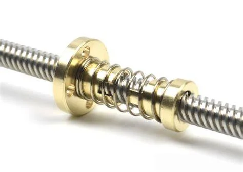
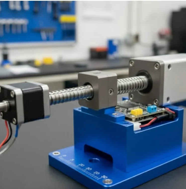
A lead screw is a mechanism consisting of a threaded shaft that rotates to push a nut linearly. Most lead screws use ACME threads (a special thread profile—square or trapezoidal—that handles loads much better than standard fastener threads).
- Important Note: Technically, you can use a standard bolt as a lead screw, but the efficiency will be very low (binding or energy loss due to friction). ACME lead screws are specifically designed for linear motion applications.
2. DESIGN CHARACTERISTICS OF LEAD SCREWS
1. Massive Gear Ratio
Screws with high thread density (more threads per inch) inherently create a massive gear reduction system. This provides tremendous pushing force at the cost of slower linear speed.
2. Multi-Start Threads
Multi-start screws feature multiple independent thread paths running parallel along the same shaft.
- Benefits of Multi-Start Threads:
- Allows the nut to travel a longer distance while the shaft rotates slower.
- Better mechanism control and minimizes shaft whip.
- Reduces severe vibrations when the shaft spins too fast.
3. Support Systems
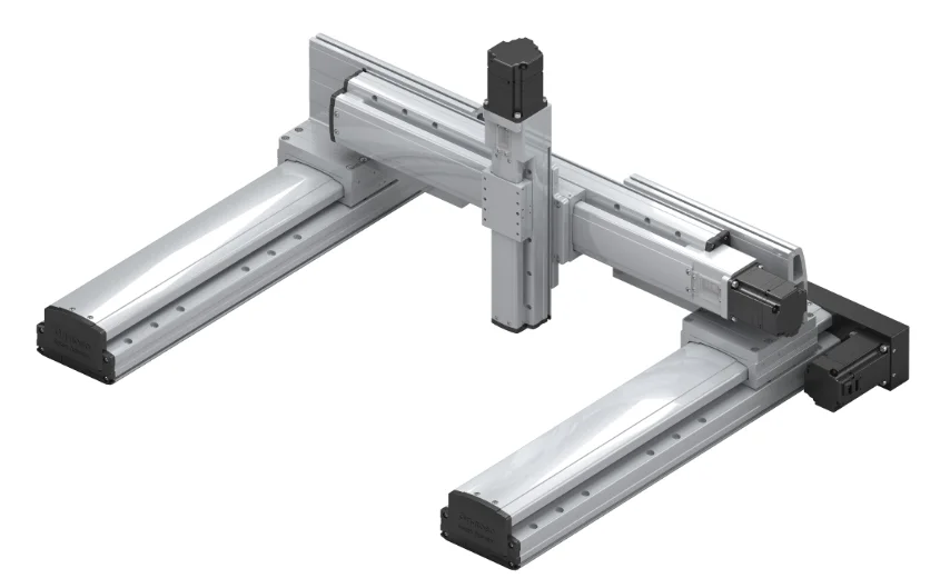
Lead screws must typically be paired with linear bearings or slide rails to keep the moving mechanism aligned and stable.
3. SPECIFICATIONS AND NOMENCLATURE
Lead screws are classified based on their diameter and pitch—the distance from the crest of one thread to the crest of the next, measured parallel to the axis.
- Nut Materials: Nuts are typically made of brass or engineering plastics. Because this mechanism relies on sliding friction between the shaft and the nut, the nut material dictates operational efficiency:
- Brass: High durability, good load capacity, requires lubrication.
- Engineering Plastics (Delrin, Nylon): Smooth operation, self-lubricating, excellent wear resistance.
4. CRITICAL SPEED
Definition:
Critical speed is the rotational speed at which a mechanical system (such as a rotating shaft) begins to resonate strongly, causing massive vibrations.
Lead screws have a critical speed threshold. If you spin past this speed, the shaft hits its natural frequency and begins shaking violently (much like a jump rope being whipped rapidly).
Formula for Critical Speed

Where:
- $N_c$: Critical speed (RPM)
- $L$: Distance between the two shaft supports
- $d$: Root diameter (the smallest core part of the lead screw)
- $C$: Constant depending on the support configuration at both ends
- $E$: Modulus of elasticity of the material
- $\rho$: Density of the material
- Factors Affecting Critical Speed:
- Shaft Diameter: Larger diameter $\rightarrow$ higher critical speed.
- Shaft Length: Shorter length $\rightarrow$ higher critical speed.
- End Fixation: Stiffer supports $\rightarrow$ higher critical speed.
- Shaft Material: Materials with a higher modulus of elasticity yield higher critical speeds.
5. PRACTICAL APPLICATIONS IN FTC ROBOTS
6. PROS AND CONS
7. DESIGN AND SELECTION TIPS
- Define Requirements: Linear speed, required pushing force, travel distance, accuracy, radial load.
- Choose Thread Pitch: Small pitch $\rightarrow$ high force, slow speed. Large pitch $\rightarrow$ high speed, low force.
- Choose Nut Material: Brass for heavy loads, engineering plastics for smooth, unlubricated operation.
- Design Guide Systems: Always use slide rails or linear bearings to handle radial loads.
- Calculate Critical Speed: Ensure operating speed is below 80% of the critical speed to avoid vibration.
- Lubrication: Use specialized lead screw grease, especially with brass nuts.
SAFETY WARNINGS
- Avoid Overloading: Lead screws can undergo permanent plastic deformation if overloaded.
- Protect from Debris: Dust and particles can jam the system.
- Monitor Temperature: Track operating temperatures during continuous high-speed runs.
- Use Brakes or Self-Locking: Ensure the system does not drift or backdrive when power is lost.