
THE COMPLETE A–Z GUIDE TO ONSHAPE FOR ROBOTICS
INTRODUCTION TO ONSHAPE
There are many computer-aided design (CAD) software platforms available today, such as SolidWorks, Fusion 360, and Onshape. However, in this tutorial, we will focus on one of the most accessible and user-friendly CAD platforms for students: Onshape.
CAD and 3D Design Interface
WHY CHOOSE ONSHAPE FOR ROBOTICS?
Cloud-Based: No installation required. All you need is a web browser and an Internet connection.
Free for Education: Eligible students can access a free Education plan with professional CAD features.
Collaboration: Multiple users can work on the same design simultaneously.
Version Control: Track changes and restore previous versions of your designs.
Ideal for FTC: Suitable for robot design, mechanical assemblies, and motion simulation.
8 STEPS TO MASTER ONSHAPE
1. CREATE AN ACCOUNT
Step-by-Step Instructions:
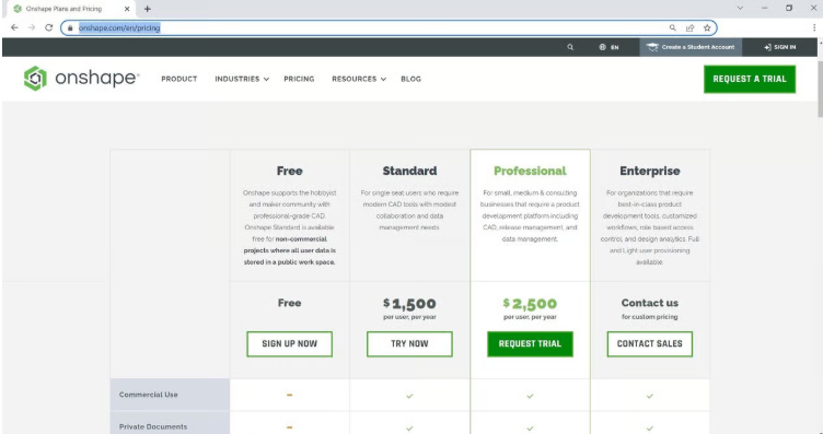
- Visit the Onshape Plans and Pricing page.
- Select Onshape Education, which is free for eligible students.
- Register using your school email address, if available.
- Complete the student verification process if required.
Creating and Registering an Account
Learning Goals:
- Successfully create an Onshape Education account.
- Understand the limitations of the free versions.
Estimated Time: 10–15 minutes.
2. CREATE A DOCUMENT
Step-by-Step Instructions:
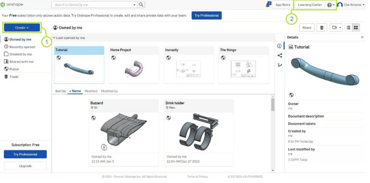
- Click "Create" → "Document".
- Give your design a meaningful and descriptive name.
- Add labels to organize and categorize your projects.
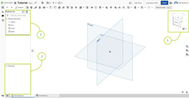
- Understand the document structure, including Part Studios and Assemblies.
Creating a New Document
Learning Goals:
- Create your first Onshape document.
- Learn how to name and organize documents effectively.
- Understand the different types of design studios.
Estimated Time: 5–10 minutes.
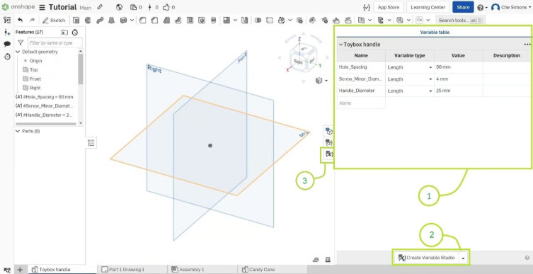
3. SET UP VARIABLES
Step-by-Step Instructions:
- Use the Variable Table to manage design parameters.
- Create variables such as
Hole_SpacingandHandle_Diameter. - Understand how Variable Studios allow variables to be shared across multiple Part Studios.
- Follow proper variable naming conventions, such as avoiding spaces in variable names.
Setting Up Variables and Parameters
Learning Goals:
- Create at least three variables.
- Understand the benefits of parametric modeling.
- Learn how to use variables in sketches.
Estimated Time: 15–20 minutes.
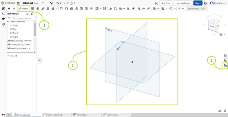
4. BASIC SKETCHING
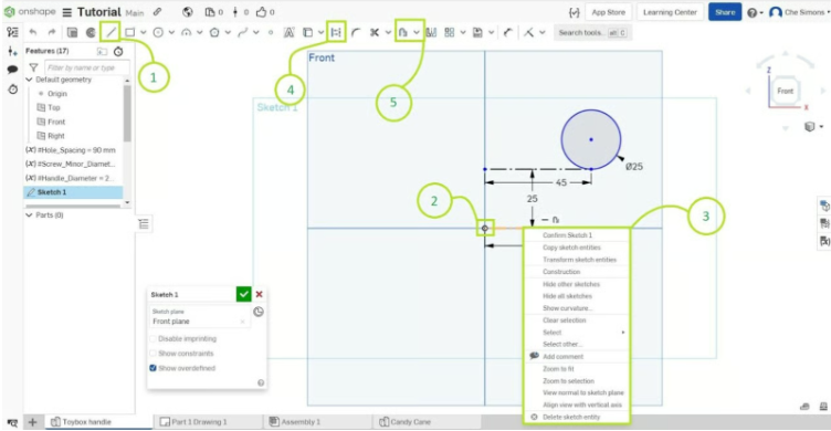
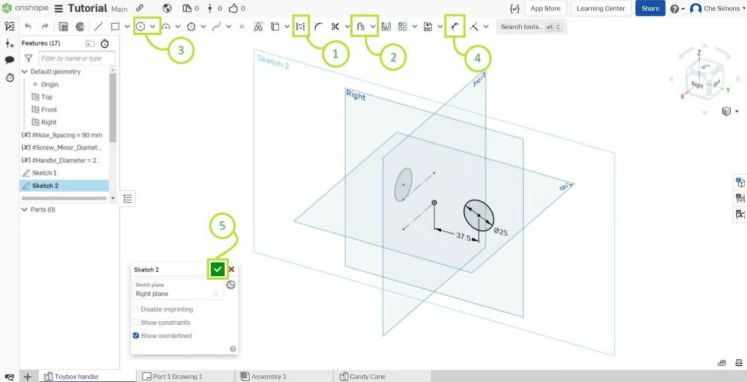
Step-by-Step Instructions:
- Select a sketch plane (Front, Top, or Right).
- Draw lines and convert them into Construction Lines.
- Use the Offset tool to create parallel geometry.
- Draw circles using their center points.
- Apply dimensions using previously defined variables.
Sketching Tools in CAD
Learning Goals:
- Create your first sketch.
- Understand the difference between Construction Geometry and Normal Geometry.
- Apply dimensions using variables.
Estimated Time: 20–30 minutes.
5. CREATE 3D MODELS
Step-by-Step Instructions:
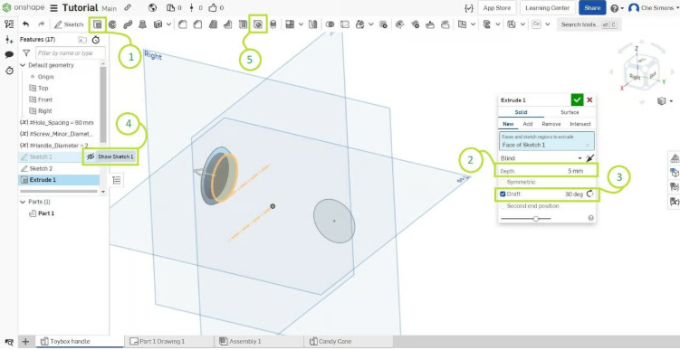
- Use the Extrude tool to create 3D geometry from a sketch.
- Add draft angles to create tapered surfaces.
- Create holes with dimensions controlled by variables.
- Use the Revolve tool to create rotationally symmetrical shapes.
- Merge multiple parts or features into a single solid body.
Extrude and 3D Modeling
Learning Goals:
- Create your first 3D part.
- Become familiar with the Extrude and Revolve tools.
- Learn how to create holes and apply draft angles.
Estimated Time: 25–35 minutes.
6. LOFTING
Step-by-Step Instructions:
- Use the Loft tool to create smooth transitions between different profiles.
- Adjust the Start and End Profile Conditions.
- Fine-tune the Start and End Magnitudes.
- Use the Mirror tool to create symmetrical geometry.
- Use the Merge with All option to combine geometry when appropriate.
Loft and Surface Transitions
Learning Goals:
- Create smooth transitions between different shapes.
- Understand the difference between Normal to Profile and Tangent conditions.
- Learn how to use the Mirror tool to create symmetrical designs.
Estimated Time: 15–25 minutes.
7. CREATE AN ASSEMBLY
Step-by-Step Instructions:
- Create Mate Connectors to define connection points between components.
- Switch to the Assembly tab.
- Insert multiple parts into the assembly.
- Apply Revolute Mates to allow rotational movement between components.
- Check the Degrees of Freedom (DOF) to ensure the assembly behaves as intended.
Creating Assemblies in CAD
Learning Goals:
- Assemble multiple parts into a complete mechanical system.
- Create and control mechanical movement within assemblies.
- Understand Degrees of Freedom and verify assembly constraints.
Estimated Time: 20–30 minutes.
8. EXPORT FILES & PRACTICAL APPLICATIONS
Step-by-Step Instructions:
- Export 3D parts into suitable formats such as STL, OBJ, or 3MF, depending on available export options.
- Create technical drawings for manufacturing.
- Select appropriate engineering drawing templates.
- Export drawings or sketches into formats such as DXF, PDF, or SVG when supported for laser cutting and other manufacturing processes.
- Prepare files for 3D printing or CNC machining.
Exporting Files and 3D Formats
Learning Goals:
- Export 3D models for 3D printing.
- Create technical drawings for manufacturing.
- Prepare design files for real-world production.
Estimated Time: 10–20 minutes.