
GEARS
Introduction
Gears are one of the most common and oldest mechanical components in engineering generally and robotics specifically. With their diverse variants, they are widely used for their ability to increase/decrease speed and torque, as well as flexibly reverse rotational direction.
To operate, two gears must mesh their teeth together, causing them to rotate in opposite directions.
"Geometrically, designing a gear can be relatively complex. However, modern CAD software features tools to make this much easier. For Onshape users, you can check out the FeatureScript: Using the Spur Gears featurescript."
1. GEAR TERMINOLOGY
Pressure Angle
- The angle between the line of action (the direction of contact force between meshing teeth) and the tangent to the pitch circles.
- Two common pressure angle values are 14.5° and 10° / 20° (standard).
- Important Note: Two meshing gears must have the exact same pressure angle.
Diametral Pitch (DP)
- The ratio of the number of teeth on a gear to its pitch diameter, expressed as the number of teeth per inch of pitch diameter.
- A larger DP means smaller, finer teeth.
- Important Note: Two meshing gears must have the same DP.
2. COMMON TYPES OF GEARS
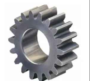
Spur Gear
- The most common and simple type. Consists of teeth parallel to the axis of rotation.
- Spur gears can only be used on parallel shafts.
- A small spur gear acting as the driver, usually mounted on the motor output shaft, is called a Pinion.
- The larger mating gear that the pinion drives is sometimes called a Bull gear.
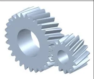
Helical Gear
- A variant of the spur gear where the teeth are cut at an angle (helix angle) across the face.
- Helical gears run smoother and quieter at high speeds compared to spur gears.
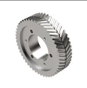
Herringbone / Double Helical Gear
- A variant created by joining two opposing helical gears side-by-side, forming a V-shape. Herringbone gears share all the advantages of helical gears while canceling out axial thrust forces.
- Highly recommended when 3D printing gears.
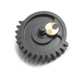
Sector Gear
- A spur gear that is not a full 360-degree circle, used in mechanisms that do not require full rotation.
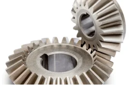
Bevel Gears
- Conical-shaped gears where a large portion of the cone tip is cut off.
- Used to transmit torque between intersecting shafts at an angle, typically ranging from 1° to 179°.
- When two bevel gears are mounted on shafts at a 90° angle and have the same number of teeth, they are called Miter gears.
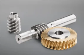
Worm Gears
- Used to achieve very high gear ratios in a compact space while transmitting torque between non-intersecting shafts perpendicular (90°) to each other.
- Consists of a worm (screw-like gear) and a worm wheel.
- Biggest Advantage: Highly resistant to backdriving (self-locking). The worm can drive the worm wheel, but the worm wheel requires enormous force to backdrive the worm.
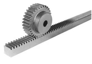
Rack Gear
- A straight bar with gear teeth designed to convert rotational motion into linear motion when driven by a pinion gear.
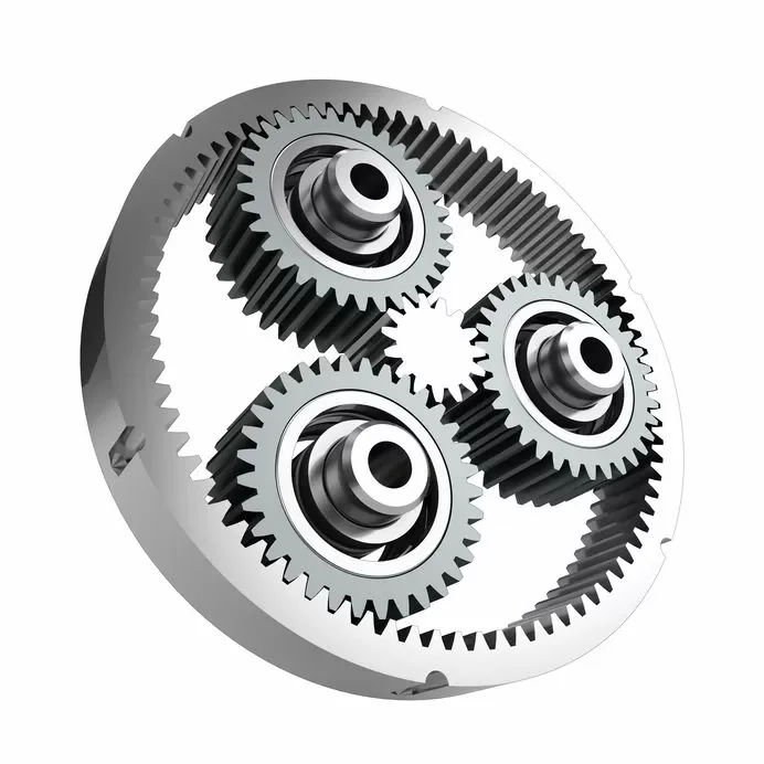
Planetary Gear Sets
- Used to achieve massive gear ratios within an extremely compact footprint.
- Consists of:
- A central Sun gear.
- Typically 3 to 4 Planet gears meshed around the sun gear.
- A surrounding Ring gear enclosing the planets.
3. DESIGNING FOR GEARS
Center-to-Center Distance
Like most power transmission methods, you must use precisely calculated center-to-center distances to transmit torque efficiently and optimally.
You can use design calculators or calculate it manually using the formula:
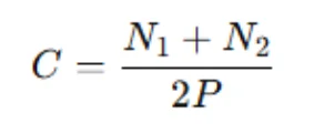
Where:
- $C$ = Center-to-center distance
- $N_1$ and $N_2$ = Number of teeth on each respective gear
- $DP$ = Diametral Pitch
Important Note:
This formula shows that only the sum of the teeth of the two gears dictates the center-to-center distance.
Example: A 50-50 tooth pair and a 60-40 tooth pair share the exact same center distance if they have the same DP.
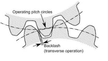
Typically, a tiny manufacturing tolerance allowance is added by increasing the center-to-center distance by about 0.003 inches (approx. 0.08 mm).
Purpose: Reduces friction and increases efficiency, at the cost of introducing a small amount of backlash.
Pitch Diameter
Another very useful approach when designing with gears is drawing them directly inside your sketches.
You can accurately model the spacing between two gears by drawing two tangent circles representing their pitch diameters.
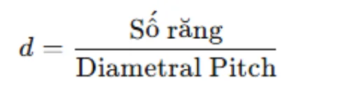
By sketching gears using their pitch diameters during preliminary layout, you get a clearer and more accurate spatial representation of your mechanism early in the design phase. Additionally, drawing the Outer Diameter (OD) of the gears is helpful for estimating clearance and physical manufacturing constraints.