
ProgrammingNov 8, 2026Trần Thế Phúc
AT#8: PULSE WIDTH MODULATION (PWM)
#Arduino#PWM#Theory#Electronics
SPECIFICATION & TECHNICAL NOTES
OVERVIEW OF THE PWM DIAGRAM
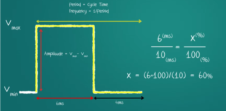
PWM (Pulse Width Modulation) is a technique that adjusts the width of electrical pulses to simulate an analog voltage. Below are the fundamental parameters of a PWM signal:
PWM Diagram: Period, Frequency, Amplitude
PRACTICE AND FORMULAS
To calculate the average output voltage (Vout), we use the Duty Cycle, which represents the percentage of time the signal remains HIGH during one period.
PWM Practice: Duty Cycle and Vout
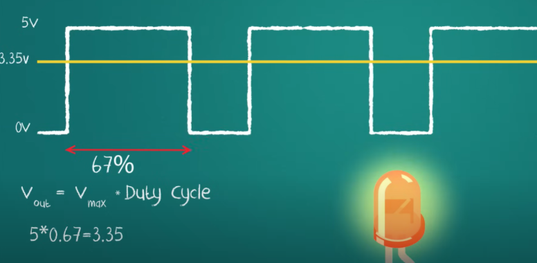
Formula:
Vout = Vmax × Duty CycleExample:
5V × 0.67 = 3.35VWith a Duty Cycle of 67% and a maximum voltage of 5V, the average output voltage is approximately 3.35V.
Verified by FTC 31113 Technical LeadID: ce940e7c-53ba-4ec1-96fb-40523ce4a2ab