
ProgrammingNov 8, 2026Trần Thế Phúc
AT#9: MEASURING VOLTAGE WITH A MULTIMETER
#Arduino#Multimeter#Voltage#Practice
SPECIFICATION & TECHNICAL NOTES
INTRODUCTION TO THE PRACTICE EXERCISE
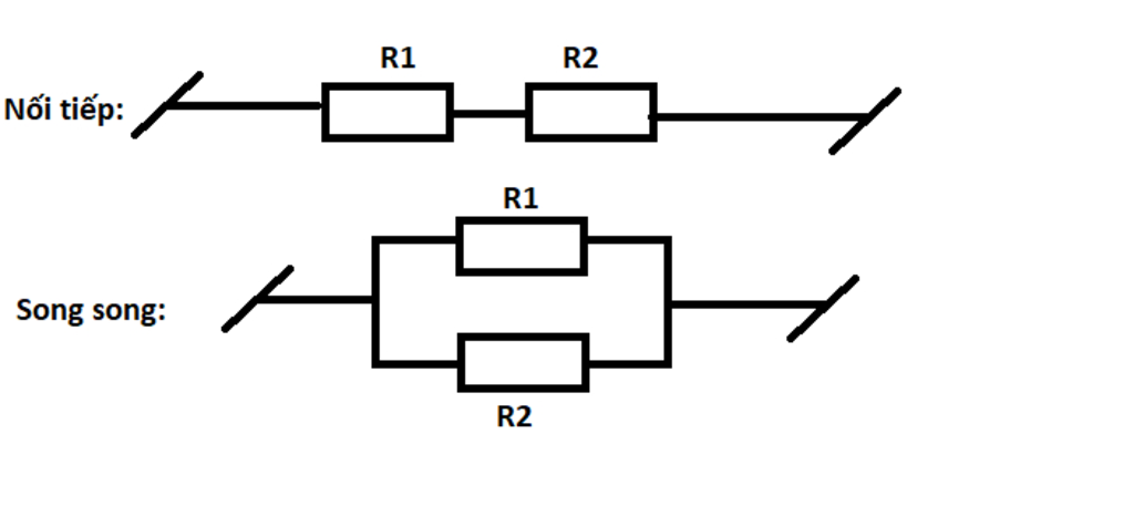
In this practical exercise, we will learn how to use a multimeter to measure the voltage between two points in a simple electrical circuit consisting of two resistors, R1 and R2, connected in series.
CIRCUIT DIAGRAM
The circuit consists of a 5V power supply from the Arduino connected to two resistors, R1 and R2. We will measure the voltage across each resistor.
Voltage Measurement Circuit Diagram
STEP-BY-STEP INSTRUCTIONS
- Prepare the multimeter: Set the multimeter to DC voltage measurement mode (V⎓).
- Connect the probes: Place the red probe at the point with higher electric potential and the black probe at the point with lower electric potential.
- Measure R1: Place the two probes across the terminals of resistor R1 to measure the voltage across it.
- Measure R2: Similarly, place the two probes across the terminals of resistor R2 to measure its voltage.
- Verify the results: The sum of the voltages across R1 and R2 should equal the supply voltage (approximately 5V).
Verified by FTC 31113 Technical LeadID: eebef545-81bf-45a0-badc-b8803ecaf161