
Tolerancing
“Proper tolerancing is a key factor in ensuring mechanical parts assemble accurately and function correctly in practice.”
Consider a simple, relatable example: designing a gift box and its lid. If the outer width of the box is designed to be 100 mm, and the inner width of the lid is also designed to be exactly 100 mm, in actual manufacturing, the lid will likely not fit or will get stuck during assembly.
1. MANUFACTURING ERRORS
This occurs because manufacturing errors are always present during fabrication:
Waterjet cutting:
The cut path often has a taper, causing actual hole or profile dimensions to be smaller than the designed size.
Laser cutting:
The machine typically cuts right along the toolpath line, which tends to make the finished dimensions larger than nominal.
Traditional CNC machining (Milling or Turning):
Allows better tolerance control, depending on machine accuracy, tooling, and machining parameters.
Therefore, if tolerances are not accounted for from the design phase, parts that appear to fit on engineering drawings may fail to assemble or operate unreliably in practice.
2.TOLERANCING CONSIDERATIONS IN MACHINING AND ASSEMBLY
Holes for bolts or rivets:
Holes are typically pre-drilled and then enlarged with a properly sized drill bit to guarantee assembly clearance.
Holes for bearings or dowel pins:
Must use a reamer to achieve precise dimensions and high surface finish.
Non-standard geometric features (such as slots and tabs):
Tolerances should be directly incorporated into the CAD design. Examples:
• Increase slot width by 0.1 mm
• And/or decrease tab size by 0.1 mm
Material thickness measurement:
Accurately measuring the actual material thickness before designing is critical.
For example, a polycarbonate sheet with a nominal thickness of 3.2 mm often has an actual thickness of around 3.0 mm.
Designing a 3.2 mm thick component to fit into a 3.2 mm slot may result in a loose fit, reducing structural rigidity.
3. REAMER
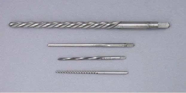
Used after drilling operations to:
- Achieve accurate hole sizing to meet specified tolerance requirements.
- Improve surface finish, roundness, and hole cylindricity.
This is an indispensable tool for high-precision mating interfaces like bearing bores and dowel pin holes.
4.TOLERANCE AND FIT HANDBOOK
A technical reference document used to:
- Look up fit types (clearance fit, transition fit, interference fit).
- Determine appropriate sizes and tolerances matching functional requirements.
- Support engineers in making sound tolerancing decisions for real-world production. For more details, you can refer here: Fits and Tolerances Handbook.
5. BASIC TOLERANCING TERMS AND CONCEPTS
- Basic Size: The theoretical nominal size used as a baseline to determine tolerances and limits.
- Limits of Size: The maximum and minimum allowable dimensions of a feature.
- Tolerance: The total allowable variation between the upper and lower limits of a dimension.
- MMC (Maximum Material Condition): The condition where a feature contains the maximum amount of material within its stated tolerance limits (e.g., maximum shaft diameter, minimum hole diameter).
- LMC (Minimum Material Condition / Least Material Condition): The condition where a feature contains the minimum amount of material within its stated tolerance limits (e.g., minimum shaft diameter, maximum hole diameter).
- Fit Tolerance: The dimensional clearance or interference between mating components at their actual material states.
6. RELATIONSHIP BETWEEN TOLERANCE AND MANUFACTURING COST
- Tolerance selection must balance functional requirements and manufacturing feasibility:
- Tight Tolerances: Require high-precision equipment, stringent process control, and sophisticated inspection methods, driving manufacturing costs up sharply.
- Loose Tolerances: Help reduce machining costs but may compromise product accuracy, alignment, and mechanical performance. The cost-tolerance curve demonstrates that as tolerances become tighter, cost increases non-linearly. Note that default dimension tolerances in CAD models are often tighter than necessary. Applying these default tolerances without sound engineering justification unnecessarily inflates manufacturing costs. Therefore, a good designer balances technical specifications with economics, choosing tolerances that are just tight enough to fulfill functionality and maintain cost efficiency.
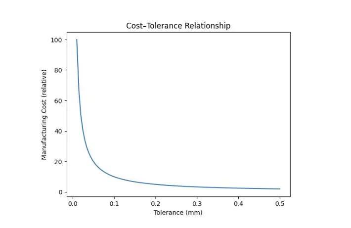
The graph above illustrates the typical relationship between machining tolerance and manufacturing cost. X-axis: Tolerance (mm) Y-axis: Manufacturing Cost (relative) As tolerance decreases (higher precision required), manufacturing cost rises sharply in a non-linear fashion due to:
- Need for higher-precision machinery and specialized tooling
- Increased cycle and machining time
- Higher inspection, calibration, and quality control costs Conversely, with looser tolerances, machining costs drop significantly, though part functionality and assembly stability must still be safeguarded.